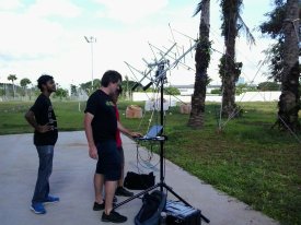
 <div style="transform: rotate(-90deg) translate(30px,280px); transform-origin: left top 0;">(Photo: Darryl Ee 9V1DE)</div>
After successfully listening to FO-29 with a handheld satellite-antenna at Geekcamp last year, I realised two things:
- directional antennas are extremely desirable for satellite work, but
- holding and pointing the antenna array by hand is exhausting.
I therefore decided to build a tracker that would automate the pointing and following work.
The resulting system came together just in time for Maker Faire, so I conducted its first tests on site. It worked first time! (It did, however, fail the second time…)
Background
Although there are all sorts of interesting things to pursue now that I have an amateur license again, I am particularly interested in space communications because of the awe-inspiring possibility that I can, directly and as an individual, interact with things in deep space. A more detailed post on my interest, reasoning, and priorities may appear at some future time, however another important detail is that I’m indulging a childhood love of electronics; a little more tinkering than is strictly necessary to achieve the communication objective is very clearly in evidence.
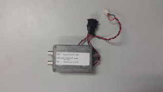
After deciding that I wanted to build a tracker, I did a little looking around and discovered that AMSAT-NA offers several items designed by Mark Spencer WA8SME who does various things within ARRL to improve classroom access to space communications. In particular, AMSAT-NA offers a circuit board and programmed microcontroller for Mark’s WRAPS (Wobbler RadFxSat Antenna Pointing System) and a ready-made pre-amp designed specifically to improve amateur satellite operation. This seemed like a sufficient recommendation for pursuing this approach. It’s worth noting that a far less time-consuming approach would have been to purchase second-hand satellite-TV gear via eBay, however this would involve rather less tinkering!
Construction
I didn’t keep accurate time records, but I’d estimate 40-60 hours of hands-on building - most of it in too much fiddling with metalwork - and another ~20 hours of related activity. By far the most difficult part for me was fabricating the aluminium components to support the two motors, one for compass direction rotation (“azimuth”), the other for vertical adjustment (“elevation”). It appears that I’ve forgotten most of what I learned about metalworking in high school.
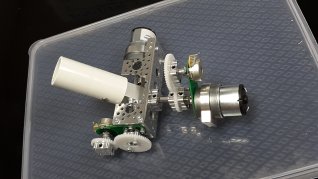
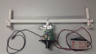
The motor assembly: azimuth motor and position sensor to the right, elevation motor towards to top, elevation position sensor towards the bottom. An interesting element of the design of WRAPS is that it doesn’t use stepper motors, instead it uses DC motors with reduction gears to 0.5RPM plus potentiometers (variable resistors) as position sensors, which is what the plastic gears are about; they’re not load-bearing. The PVC pipe to the left is what the antenna array will be attached to. The aluminium channel will be mounted on a ball bearing turntable, itself on top of a metal box that the azimuth motor will also be bolted to.
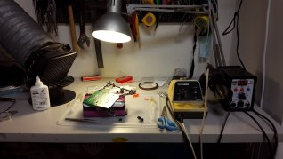
The controller board uses a mixture of through-hole and surface-mount devices. Although I learned to solder when I was 7 years old, this was my first ever experience with soldering surface-mount devices. A huge thanks to Adnan for lending me his heat gun (the tool to the right, sleeping (“SLP”) at the time of the photo) for this purpose. Other notable items in the photo include:
- The solder paste (grey, to the left) and tack flux (yellow, to the right) in syringes. The flux comes with all sorts of warnings about its being a respiratory irritant when heated, which is the reason for the exhaust fan and duct. Despite the precautions I did manage to get a whiff of the vapour in my nose and eyes, which was an eye-watering experience. Think super-strong liniment but with an unpleasant, acrid smell. It’s not something that I’d want to work with on a daily basis, but it certainly does the job: I’ve never seen solder flow so readily.
- The helping-hands holding the board, and the magnifying lens (separated and to the left at the time of the photo). Surface-mount capacitors and resistors can be astonishingly small.
- The tweezers near the front, for the same reason.
- Roll of Kapton tape near the rear. This makes it possible to protect existing solder joints that attach existing components which happen to be in the path of the 340°C air stream out of the heat gun when attaching an additional component. Without this protection, the solder attaching adjacent existing components will melt, and the movement of the air from the heat gun will cause the components to start to sail away on tiny solder lakes. Legitimate excuse to use a material developed for the Apollo Program pleases me no end. Note that it is more usual to perform initial soldering of surface-mount devices in a soldering oven, exactly because the air rushing out of the heat gun risks pushing components around, however I was unable to borrow one and - although I could make one (and HackerspaceSG already has a toaster-oven earmarked for this purpose!) - soldering the small number of surface-mount components required with a heat gun was a simpler approach.
The assembled system
(Apologies to non-technical readers for the following technobabble.)
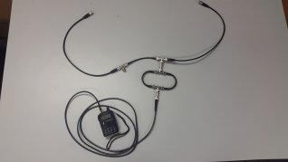
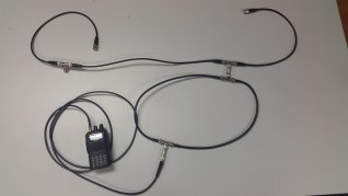
- The antennas are a pair of Arrow 146/437-10BP portable antennas, without duplexers. The use of two phased perpendicular antennas on each band solves the problem of having to match alignment with the satellite’s antennas. Instead of adding a complex mechanism to twist the antenna (as was done by hand at the Geekcamp demo), or doing without and suffering serious fading a lot of the time, the pairs of antennas linked with phasing harnesses provides circular polarisation, both CW and CCW, to provide workable communication in almost all circumstances.
- There are separate but equivalent coax harnesses for 70cm and 2m:
- In each case, a 50Ω segment from one driven element, a T-piece, a 50Ω ƛ/4 phasing line, another T-piece, and another 50Ω segment - same length as the first one - to the corresponding driven element on the other boom.
- CW polarisation is therefore available at one T-piece, CCW at the other. Unfortunately the presented impedance is 25Ω (2 * 50Ω in parallel), so I added an impedance transformer - consisting of a 37.5Ω ƛ/4 coax segment - to get back to 50Ω to connect the radio. As 37.5Ω coax is not readily available, the transformer is actually a pair of 75Ω ƛ/4 segments in parallel, connected at each end with appropriate T-pieces etc.
- A further ~2m of 50Ω coax connects each of the radios, one for 2m uplink, one for 70cm downlink.
- The ƛ/4 lengths were all worked out in my head - with wild guesses about the internal lengths of the BNC connectors and T-pieces - at the time that I ordered the cables. (My cable termination skills are not yet excellent; I decided that this was an area of uncertainty that I didn’t want to deal with this time around so I had them made professionally at Sim Lim Tower.) Some testing with Royce Ng 9V1AN’s VHF antenna analyser suggests that the whole 2m harness is within a few % of optimum!
- The radios are a pair of VHF/UHF handhelds.
- I realised on the day that I had made the leads to the pre-amp too short to remain connected to power as the antenna array moves, so I did without. As the tests were only with high passes, this was not a significant constraint.
- One part of the WRAPS design was not clearly described and not illustrated (some sort of hand-made coupler inside a metal tube), so I improvised the antenna mount from PVC pipe that I happened to have lying around, and some cotter pins made from spare aluminium tube at HackerspaceSG. The result works, but it could politely be described as rickety; the antennas wobble through several degrees of play on their own as the tracker moves them around.
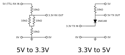
- The circuit board supplied by AMSAT-NA is for a later version of the design than what’s described in the article. In particular, the USB UART has been replaced with a socket for an XBee to overcome noise problems when working packet modes. I’m not yet working packet modes and had a USB->TTL-serial cable lying around, so improvised a daughter board to sit in the XBee socket and receive the TTL end of the cable. As the XBee uses (and the PIC microcontroller requires) 3.3V signalling, and as I had a pile of 10KΩ resistors to hand, I also improvised a voltage-divider to convert 5V to 3V with 4 * 10KΩ resistors. As the interface is one way, I did not need to do the reverse, although I did locate a circuit to do so with a resistor and a diode.
- The stand is an ordinary speaker stand, the shelf for the notebook is actually from a music stand, suspended with string and a pair of surplus 3D-printed spanners lying around in HackerspaceSG (the blue things at the bottom of the strings). Unfortunately, the duct tape holding the shelf in place wasn’t an adequate solution and - when someone leaned on it - I very nearly had my notebook hit the concrete, so I switched to using the music stand in its original configuration (on its own tripod) the next day.
- Obscured by my bag is a 7Ah 12V lead-acid gel battery, which is massive overkill for running the motors and microcontroller, but it did the job!
- Unfortunately the only driver which currently exists for the WRAPS controller is embedded in the closed-source SatPC32 which, as its name suggests, only runs on Windows. Fortunately Microsoft now provides free, time-limited images of multiple Windows and Explorer versions, packaged for common virtualisers on Windows, OSX and Linux. Getting this running on my notebook took all of 15 minutes. Adding SatPC32 was straightforward.
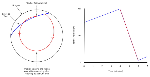
Getting my head around rotator geometry and turn points took considerably longer than installing SatPC32. The rotator has only 360° of azimuth freedom. This is fine if you just want to be able to point in a selected direction and don’t mind waiting a minute or two to get there, but a problem if you want to smoothly follow a satellite across the sky and the satellite’s track happens to cross the tracker’s azimuth limit, as the tracker then has to then stop tracking, turn almost 360° in the other direction, and then resume tracking, losing communication for a minute or two. There are 450° and 540° trackers available specifically to address this problem, but WRAPS is intended to be a little simpler so - like many simpler trackers - the idea is decide per-pass whether 0° is north or south, pick up and turn the whole system around to match the decision, tell the microcontroller (there’s a switch on the board), and tell SatPC32. An hour of fiddling at HackerspaceSG got this straight in my head.
The first test
Most of Saturday was tied up with setting up the HF station in the field to the right (out of frame in the picture at the top), so the satellite test was a little rushed. I:
- assembled the system,
- positioned it with 0° as north,
- set switch to turn-point switch to north,
- configured SatPC32 to assume that 0° was north,
- selected an approaching satellite,
- pressed F (follow),
- tuned one radio to receive, and
- waited.
Sure enough, as the satellite cleared the horizon, the antenna array began following it and we could clearly hear the beeps and warbling of a digital mode for as much of the pass as our position would allow the system to follow (there was a building behind me in the picture at the top, so we couldn’t follow it all the way). I was both thrilled and suspicious that a system this complex worked on its first test, nothing with this many separate parts ever works first time…
The second test
I went through pretty much the same process on Sunday afternoon, except that I also connected and tuned a second radio for uplink. Unfortunately the result was rather different; the system somehow swapped horizon and zenith (directly overhead), so it pointed the antennas up as the satellite cleared the horizon and gently lowered them towards the horizon over several minutes as the satellite climbed. There was a little over a minute at ~45° elevation where we could hear a conversation in progress, however I couldn’t hear my own calls (part of the benefit of the dual-band operation used by most amateur satellites is that it’s possible to hear your own calls as you make them, which also allows you to determine that everything is working, or not as in this case).
This creates one of those unfortunate situations where it’s not at all clear what went wrong, and worse, where it’s also not clear why the system ever worked. Hopefully there’s just a SatPC32 configuration setting that got itself flipped at some point. I assume that it’s capable of dealing with trackers that treat 0° as the horizon as well as those that treat 0° as directly overhead, meaning that there will be a configuration setting to indicate this. I’m certain that I would have noticed that the antennas had been pointing in the wrong direction during the first test!
Next Steps
Several things need doing before I’m willing to declare the tracker working:
- Working out what went wrong during the second test is the first priority.
- Writing an open-source driver to allow Gpredict to send commands to the WRAPS controller will mean that I can dispense with SatPC32 and therefore Windows. Not only does Gpredict run on Linux, it’s also a rather more modern design and more pleasant to use. The “32” at the end of SatPC32’s name gives away its vintage, and it certainly has the now-klunky feel of a mid-‘90s application, plus a couple of decades of “barnacles” in the form of roughly-added capabilities.
- Completing the original steel-tube based mounting of the antennas will improve the stability of the antennas.
Future Projects
-
The need to use a notebook seems excessive (and was nearly rather expensive) as all that it’s doing is (a) allowing target satellite selection, and (b) sending a azimuth/elevation commands to the microcontroller every few seconds while tracking. There are already mobile apps for doing the first, it would seem like a very small step to add a Raspberry Pi to take care of the second and to sort out a means for a mobile app to tell the Pi to start tracking a specific satellite.
-
I’m half tempted to add a feedback channel to the controller board to allow Gpredict to monitor where the antennas are actually pointing (there can be a delay of more than a minute between telling to tracker to point somewhere and the antennas actually pointing there) and to know the current position of the turn-point switch on the controller, or indeed, to enhance the protocol to simply tell the controller where the turn point is.
-
That said, the 360° azimuth constraint bothers me, I’d rather not have to pick up and reorient the entire system every couple of passes. Since starting to build the WRAPS I have discovered the SatNOGs project which - in addition to publishing more contemporary designs that are far easier to modify (all complex parts are 3D-printed, the required metalwork is just hacksaw-cut aluminium-channel, a Beaglebone as controller, …), and are weatherproof (WRAPS is not) - is also building a global network of Internet-connected ground-stations. All of this cool stuff is not enough reason to do it now, although I rather wish I’d noticed the project before I started down the WRAPS path, however if their design can easily support 540° azimuth operation, then I’ll be strongly tempted to build one.
-
I’m also impressed by designs like this one by Julie VK3FOWL and Joe Gonzales VK3YSP with its own sensor feedback (more details at their projects page) to work out exactly where it’s pointing. So many choices!
-
Naturally, I have an even crazier idea in mind: to produce a zero-moving-parts design that uses a dozen dipoles arranged in a geodesic dome, purpose-built shared-oscillator radios, and beam-forming to perform all pointing. I’m not quite ready to start this…

