
Background
This post is about part of the ongoing work to get the SARTS VHF repeater 9V1RS near Dover working more reliably and with greater coverage. A particular concern is apparent interference very close to the repeater input frequency 145.025MHz:
<img src=”/2019/05/12/Apparent interference at 9V1RS site.jpg” width=50%>
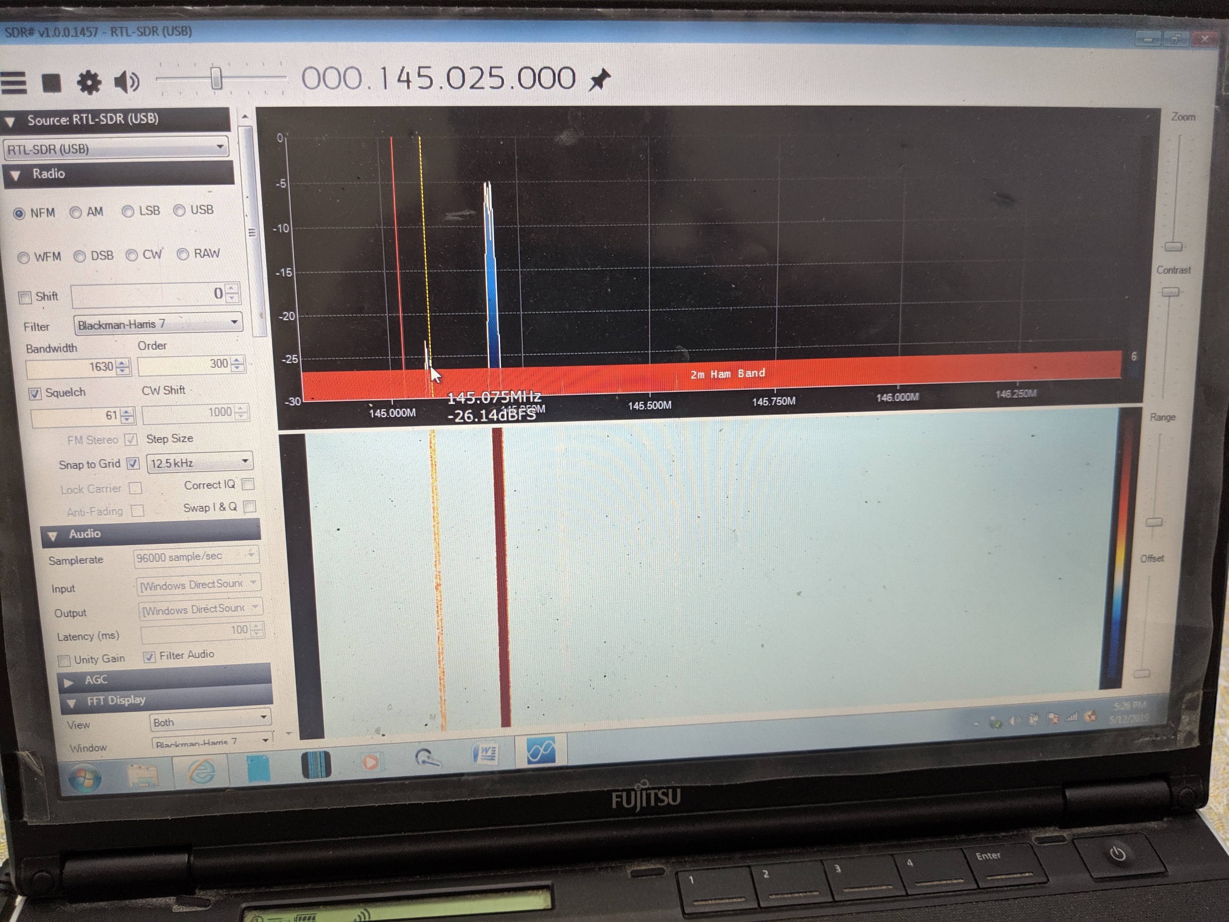
Note the ~15KHz wide signal centred at ~145.075MHz, and the much stronger ~30KHz wide signal centred at ~145.185MHz.
Tests in May
Several months ago I observed an interfering signal very close to the repeater’s input frequency (145.075MHz vs. 145.025MHz), which might conceivably push the receiver’s AGC down to the point that weaker on-frequency signals fail to successfully lock the PLL so the receiver would not successfully demodulate them. This hypothesis is consistent with the observed low-sensitivity symptom, but testing it would require assessing the relative power of the on-frequency and interfering signals and then determining whether the margin was will inside the receiver’s selectivity. I was unable to test this at the time because:
- I had not arranged for any of the stations that can reliably work the repeater to be available to send test signals.
- Jaya’s SDR is apparently emitting enough conducted noise on VHF that the setup was causing the receiver to detect a busy channel and therefore not operate as a repeater at all. (Adjusting the squelch hadn’t occurred to me at that time, although it would likely worsen the underlying problem anyway.)
- My spectrum analyser had taken it upon itself to cease functioning while at Jaya’s place. (Naturally it resumed working as soon as I put it back onto my table at HackerspaceSG. Hauling a 20kg instrument around is a pretty unappealing option anyway.)
- Further, my spectrum analyser does not provide a waterfall display, making the potentially interfering signal difficult to recognise, let alone measure.
Changes in approach
To address these issues, I:
- Ordered a 19.5dB (~99:1) directional coupler.
- Sorted out how to use my LimeSDR as a spectrum analyser - including a waterfall display - so I could (a) test it before visiting and (b) easily carry it. In particular, I sorted out software and configuration to use GQRX as a waterfall display.
- Requested that volunteers be available to send test signals for yesterday’s visit.
What I learned
Gain control
The most important thing that I learned was that it is necessary to have control of the SDR’s gain when performing measurements like this. Spectrum analysers are set up this way (center frequency, frequency range, and gain being the three controls common to almost all spectrum analysers), however GQRX is not. Worse, there are multiple gain stages before the ADCs in the LMS7002M (at least the trans-impedance amplifier and the low-noise amplifier) so even working out what to adjust was not something that I could do quickly, let alone how to do it in the multiple layers of software between GQRX and the chip.
Sadly I failed to save my screenshots (I have since corrected the print-screen configuration on my laptop so that future screenshots are written immediately to disk…), but the gist of it is that, for whatever gain levels were in use, the output of the repeater was appearing about 40dB above the SDR’s noise floor, while the input wasn’t appearing above the noise floor at all. The immediate solution to this problem is to increase the gain in the SDR, which requires more study on both approach and on control of the chip. Further, there appears to be an AGC in play as switching from the directional coupler to the splitter - which should have increased the signal presented to the SDR by 17dB - didn’t materially change the results.
Interfering signal appears to have disappeared
Additionally, the 145.075MHz interfering signal did not appear to be present during these tests, suggesting that it may not be the cause of the problem anyway.
So what now?
I’m not at all sure what this means for correction of the problem. I do note that a surprising amount of power at the output frequency is present on the RX side of the cavity filter and wonder it might be useful to add further filtering. Traditionally this has meant more cavities, but this is bulky and costly and not terribly appealing as a starting point. I’m aware of people using very carefully trimmed ƛ/4 coax stubs, particularly at the lower-power part of the system (i.e. after the cavities have removed most of the transmitter power), and suspect that there are also digital filters with very steep rolloffs, but couldn’t quickly locate any usable examples.
Keeping leads to a minimum
I also made an error that only occurred to me in retrospect: the cable from the cavity filter to the receiver is LMR-400, which typically provides about 90dB of isolation from interfering signals around the cable. Rather than connect the SDR directly to the coupler, I used a 2m RG-58 patch lead. It’s isolation is unknown, but I’d suggest that it’s at least 10dB worse, meaning that the test setup with the directional coupler was probably adding material transmitter power to the SDR’s input, and the test setup with the splitter may well have been worsening the underlying problem by injecting transmitter power into the receiver. Things to avoid next time…
Next steps
Antenna change
First and foremost, we’re approaching the point where we can replace the current discone antenna with a purpose-built dual-band antenna. To complete this, we need to do something like:
- Complete drawings showing the proposed installation works. Siva is working on these, with a little luck they should be ready this week.
- Submit the drawings and supporting details to IMDA for approval.
- Submit the drawings and supporting approval paperwork to HDB for approval and then to the West Coast Town Council.
- Book security etc. and have our contractor perform the installation work.
- Complete follow up paperwork.
Better measurement
This is about finding/creating more suitable spectrum analysis software for the LMS7002M, in particular to work out how to control the gain and to do so.
Filtering
This requires research into low-power filtering options that can be used in the presence of the transmitter. It’s not necessary to control the 35W conducted emissions from the transmitter as the cavities already do that, but it is necessary to avoid absorbing radiated emissions that are leaking all over the place and coming directly from the antenna nearby.
Improving the cavity-radio patch cables
There are several issues:
- The cables are so short that it’s not possible to look directly at the connectors while plugging the radio in. Using a smartphone front camera to locate sockets and then doing it by feel are workable, but every movement of the repeater stresses the cables and connectors.
- The cables are LMR-400 which provides good isolation but is also fairly rigid, meaning that it is not ideally suited to connection to the back of a repeater that needs moving from time to time.
- The stresses have been sufficient that both the RX and TX cables have come out of the back of their respective N connectors at different times. We’ve tested the TX side and verified that very little power is being reflected, so the “carefully push it back together” approach is working, but is hardly desirable. It remains conceivable that this problem on its own is responsible for the low-sensitivity problem. (We can’t test the RX lead for reflected power the same way we tested the TX lead; if the slightly loose connector is allowing transmitter power in then that would invalidate the benefit of the high-isolation cable anyway and contribute to desense.)
I have in mind replacing them with something like 5m each of Messi Ultraflex 10. This provides plenty of slack for work access, physical flexibility to avoid stressing anything, and as a handy side-benefit provides a further 15dB of isolation.
Comments welcome!
I am, obviously, learning as I go here. I would appreciate informed input!